Last updated at Tue, 19 Dec 2023 21:49:15 GMT
Welcome back to the car hacking development workbench series. In part two we discussed how to read wiring diagrams. In part three, we are going to expand on the workbench by re-engineering circuits and replicate signals used in your vehicle.
If this is your first time stumbling across this write up, I encourage you to check out the previous two parts to this series:
Part 1: Constructing a Workbench
Part 2: How to Read Wiring Diagrams
Re-engineering Circuits
There are hundreds of sensors and switches on a vehicle. It would be impossible to describe how to re-engineer all of them, but there are a few types of circuits that are reoccurring. This section will describe two common types of circuits that you may want to add into your workbench.
Switches

Just like a light switch on the wall, a vehicle switch has an open and closed state. In the open state, the circuit is not complete and the light (or sensor) is in the off position. In the closed state, energy traveling down the line is connected to the ground point. It is a complete circuit and the light (or sensor) is in the on position.
Let's explore the implementation of a switch in a real case scenario using the seat belt diagram above.
An illuminated 12v switch is a great starter circuit if you are unfamiliar with basic circuitry. There are three connection points to the switch pictured below:
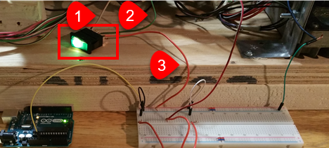
1. This is the RD/LG wire from pin 24 originating from back of the instrument cluster and connected to prong 1 of the lighted switch.
2. This green wire was added to the system and runs directly from the second prong of the switch to the PDC, as this is supplying the workbench with a 12V power supply.
3. The third prong of the 12V switch connects to ground. In the picture above, the orange wire is fed into the negative rail of a breadboard; however, it could have been directly linked to any available grounding point if it completed the circuit. A breadboard is a plastic electrical distribution tool used for prototyping circuits and can be purchased from electronics stores at a fairly cheap price.
Variable Resistor (Potentiometer)

Variable resistors channel power through a media, where the voltage of that power source can change. This process of changing voltage levels can be controlled using a potentiometer. Therefore, by substituting potentiometers for dials and sensors, we can replace the sensors that we left behind on the vehicle. For this example, we are going to control the fuel gauge using a potentiometer.
1. I used an Arduino Uno to provide a battery-drive, 5V signal to pin 1 of the potentiometer; however, you could use a power source from the chassis and achieve identical results.
2. Pin 2 is connected to the instrument cluster's pin for the fuel gauge.
3. The third pin is connected to ground. Pictured, the third pin jumps and connects to the breadboard's grounding rail, but could have just as easily been connected to any ground point directly.
With the workbench and the key in the on position, the instrument cluster will read the voltage from pin 2 of the potentiometer and adjust the gas gauge accordingly. So, by turning the knob on the potentiometer back and forth, we can adjust the fuel level.
Pitfalls and Shortcomings
Let me save you from going completely bonkers later by explaining some of my difficulties in this project:
1. It was working before. Why will it not work now?
You have either entered the Twilight Zone, or your circuit is no longer grounded. When I was building my bench, I didn't know what I could and couldn't cut, because of all the tape and fire hose wrapping on the electrical harness. As described earlier, I recommend removing these wrappings. However, I was not careful enough, and accidentally sliced into wires that were necessary to complete circuits that I tested later. After initial testing looked good, I moved the wires out of the way, only to find that the circuit didn't work anymore. Fortunately, it's a quick fix: just trace the wire and splice the broken pieces together. Another fault that occurred a couple of times was when an exposed (barren) wire would accidentally ground against something that it wasn't supposed to, so wrap any exposed splices or joints.
2. What is this and where did it come from?
I will definitely go back and do this project again. But, I will make sure that I label absolutely everything! I know that I spoke about labeling before, but here are some quick suggestions to help the labeling process:
a. At every connector, label where it came from or where it was connected (e.g., “Right driver door,” “AC ventilation switch,” or “In cabin on floor, towards shifter.”
b. When cutting cable veins (or removing a connector that is no longer needed): label both sides of the wires were cut with a matching 4 or 5-digit number. This will ensure that you know exactly where the wires came from and ease the workflow of repairing circuitry in the future.
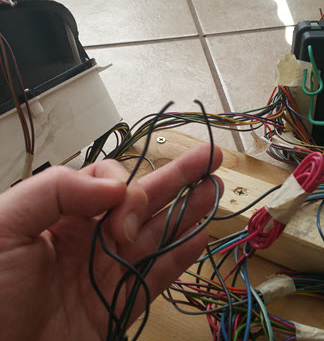
c. Black cables are usually grounding wires. Many of them are connected and then tied directly to the body of the vehicle.
3. Is adhesive tape your friend or enemy?
Removing the tape from the harness was easy, but time consuming. The worst part of the entire process was the stickiness. No matter if your vehicle is 1 year old or 15 years old, the tape will be sticky. The tape residue will eat at your hands, embed itself in your clothes or hair, and be messy. I suggest wearing disposable gloves, tying your hair back (if needed) and wearing old grubby clothes. Now, if you think that sounds horrible, try using tape for labels… ha! Tape can go over the sticky residue of previous wires, but tends to lose its own stickiness when applied over dirty wires. Clean the area you are going to apply tape to first.
Bench Complete. Now What?
It's not just a fancy 40lb paperweight. It's a learning tool and developers' playground. If you have never connected to a vehicle CAN Bus, now is the perfect time; however, you are going to need a few items first. Most cars don't have a USB interface like a computer. There are two primary types of connectors for on-board diagnostics, an On-Board Diagnostics port (OBD-II) or a J1939, as shown below.
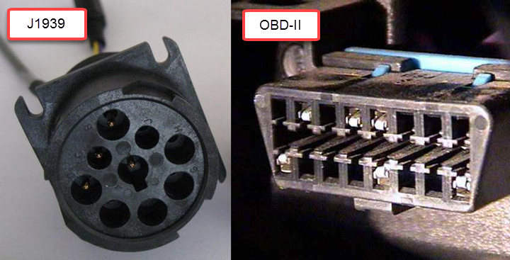
It is more likely that your vehicle has the standard OBD-II port, as the J1939 port is typically reserved for large trucks, farm equipment, and construction equipment. We are going to focus on the OBD-II. To connect a computer or laptop to an OBD-II you will need a USB-2-CAN device and software capable of interpreting the packets on the CAN Bus. Craig Smith, Research Director of Transportation Security at Rapid7, published a phenomenal book, “The Car Hackers Handbook”, that covers interaction with the CAN bus, hardware needed, packet injection, and more!
Now that you know how to create your own test bed and connect into the CAN Bus, you can begin reversing and experimenting with the car's electrical components. For more on this, see the resources section below.
Resources
Here are some good videos on YouTube to get started with:
https://www.youtube.com/watch?v=ZHaxv-cGZFI
https://www.youtube.com/watch?v=U1yecKUmnFo
Other Resources:
- Car Hackers Handbook, Craig Smith (ISBN-13: 978-1593277031)
- OpenGarages.org
- Wilson's Database